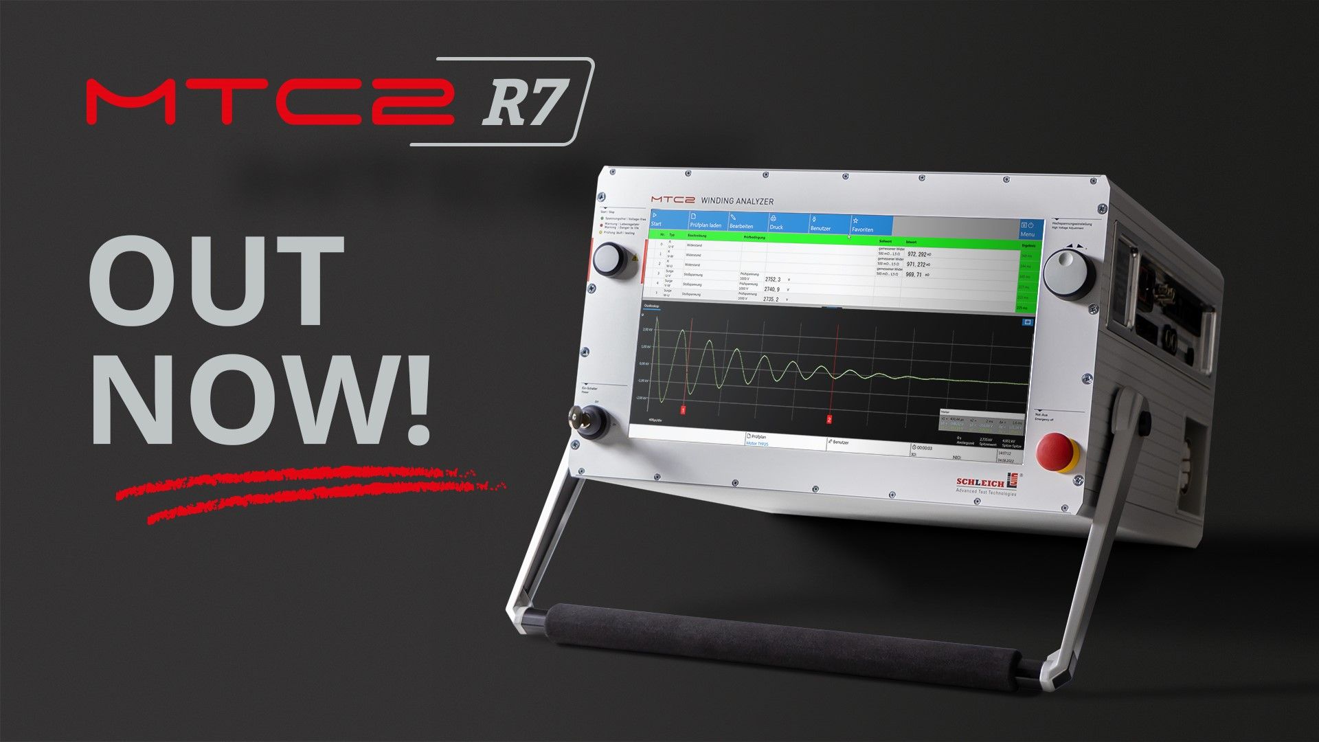

The MTC2 R7 redefines surge voltage testing
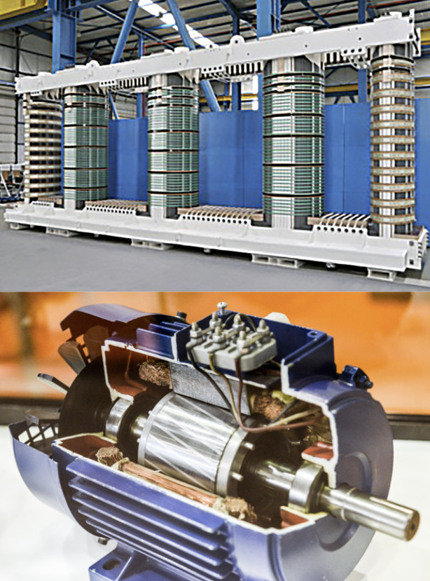
A deeper look into the winding – the surge voltage tester par excellence – the ultimate surge tester. No other tester offers so much performance variety. Reliably test stators, armatures, coils and windings of all kinds. Over 40 years of pioneering spirit, deep know-how, consistent optimization and permanent R & D activities of our engineers and technicians are the basis for this state-of-the-art surge tester.
Designed & Made in Germany.
Trailblazing surge voltage test The latest hardware technologies paired with state-of-the-art .NetCore software come into play. This significantly increases the accuracy of the individual test methods and of the measurement speeds.
The MTC2 R7 is the high-end device for testing windings, coils and armatures.
SCHLEICH PATENT:
The surge voltage test is capable of a pulse frequency of up to 50 Hz. The test time of the partial discharge inception voltages can thereby be reduced by up to 75 %.
SCHLEICH PATENT:
The SCHLEICH “peak to peak” method for the detection of voltage-dependent winding faults has been completely revised and enables highly sensitive fault detection even in the case of coils with very high numbers of windings, connected in series or parallel.


MTC2 R7 Variants

MTC2 R7 6 kV
surge test 0–6 kV
resistance 4-wire measurement
Inductance Capacitance Test NO
insulation 0–6 kV ˭max. 500 GΩ
polarization index Vmax like surge test
high voltage DC 0–6 kV ˭
test terminals T1, T2, T3, Y, frame
test cover possible
delivery order-related manufacturing
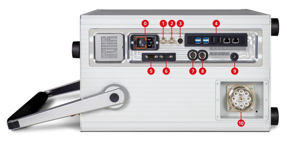
Test leads plug-in on the right side of the device
Number of test leads 5 | automatic switch-over in the test device
Housing test lead 1 | stator/motor frame
Kelvin clamps optional
Surge capacitance 100 nF; customer-specific adaptation possible
Surge energy 1,8 J
Surge current 800 A; customer-specific adaptation possible
Pulse rise time 100 – 500 ns; according to IEC 60034-18-41
Refresh rate 5 – 8 Hz
Partial discharge
—

MTC2 R7 6 kV | RLC
surge test 0–6 kV
resistance 4-wire measurement
Inductance Capacitance Test YES
insulation 0–6 kV ˭max. 500 GΩ
polarization index Vmax like surge test
high voltage DC 0–6 kV ˭ test terminals T1, T2, T3, Y, frame
test cover possible
delivery order-related manufacturing
Test leads plug-in on the right side of the device
Number of test leads 5 | automatic switch-over in the test device
Housing test lead 1 | stator/motor frame
Kelvin clamps optional
Surge capacitance 100 nF; customer-specific adaptation possible
Surge energy 1,8 J
Surge current 800 A; customer-specific adaptation possible
Pulse rise time 100 – 500 ns; according to IEC 60034-18-41
Refresh rate 5 – 8 Hz
Partial discharge
—

MTC2 R7 6 kV | PD
Test methods Surge · R · PD
surge test 0–6 kV
resistance 4-wire measurement
Inductance Capacitance Test NO
insulation 0–6 kV ˭max. 500 GΩ
polarization index Vmax like surge test
high voltage DC 0–6 kV ˭ test terminals T1, T2, T3, Y, frame
test cover possible
delivery order-related manufacturing
Test leads plug-in on the right side of the device
Number of test leads 5 | automatic switch-over in the test device
Housing test lead 1 | stator/motor frame
Kelvin clamps optional
Surge capacitance 100 nF; customer-specific adaptation possible
Surge energy 1,8 J
Surge current 800 A; customer-specific adaptation possible
Pulse rise time 100 – 500 ns; according to IEC 60034-18-41
Refresh rate 40-50 Hz
Partial discharge YES

MTC2 R7 12 kV | R
surge test 0 – 12 kV
resistance 4-wire measurement
Inductance Capacitance Test NO
insulation 0 – 12 kV ˭max. 500 GΩ
polarization index Vmax like surge test
high voltage DC 0 – 12 kV ˭ test terminals T1, T2, T3, Y, frame
test cover possible
delivery order-related manufacturing
Test leads plug-in on the right side of the device
Number of test leads 5 | automatic switch-over in the test device
Housing test lead 1 | stator/motor frame
Kelvin clamps optional
Surge capacitance 100 nF; customer-specific adaptation possible
Surge energy 7,1J
Surge current 800 A; customer-specific adaptation possible
Pulse rise time 100 – 500 ns; according to IEC 60034-18-41
Refresh rate 5 - 8 Hz
Partial discharge
-

MTC2 R7 12 kV | RLC
surge test 0 – 12 kV
resistance 4-wire measurement
Inductance Capacitance Test YES
insulation 0 – 12 kV ˭max. 500 GΩ
polarization index Vmax like surge test
high voltage DC 0 – 12 kV ˭ test terminals T1, T2, T3, Y, frame
test cover possible
delivery order-related manufacturing
Test leads plug-in on the right side of the device
Number of test leads 5 | automatic switch-over in the test device
Housing test lead 1 | stator/motor frame
Kelvin clamps optional
Surge capacitance 100 nF; customer-specific adaptation possible
Surge energy 7,1J
Surge current 800 A; customer-specific adaptation possible
Pulse rise time 100 – 500 ns; according to IEC 60034-18-41
Refresh rate 5 - 8 Hz
Partial discharge
-

MTC2 R7 12 kV | R | PD
Test methods - Surge · R · PD
surge test 0 – 12 kV
resistance 4-wire measurement
Inductance Capacitance Test NO
insulation 0 – 12 kV ˭max. 500 GΩ
polarization index Vmax like surge test
high voltage DC 0 – 12 kV ˭ test terminals T1, T2, T3, Y, frame
test cover possible
delivery order-related manufacturing
Test leads plug-in on the right side of the device
Number of test leads 5 | automatic switch-over in the test device
Housing test lead 1 | stator/motor frame
Kelvin clamps optional
Surge capacitance 100 nF; customer-specific adaptation possible
Surge energy 7,1J
Surge current 800 A; customer-specific adaptation possible
Pulse rise time 100 – 500 ns; according to IEC 60034-18-41
Refresh rate 40 - 50Hz
Partial discharge
- yes
MTC2 R7 15 kV | R | PD
Test methods - Surge · R · PD
surge test 0 – 15 kV
resistance 4-wire measurement
Inductance Capacitance Test NO
insulation 0 – 15 kV ˭max. 500 GΩ
polarization index Vmax like surge test
high voltage DC 0 – 15 kV ˭ test terminals T1, T2, T3, Y, frame
test cover possible
delivery order-related manufacturing
Test leads plug-in on the right side of the device
Number of test leads 5 | automatic switch-over in the test device
Housing test lead 1 | stator/motor frame
Kelvin clamps optional
Surge capacitance 100 nF; customer-specific adaptation possible
Surge energy 11,25J
Surge current 800 A; customer-specific adaptation possible
Pulse rise time 100 – 500 ns; according to IEC 60034-18-41
Refresh rate 40 - 50Hz
Partial discharge
- yes